Original: $0.30
-67%$0.30
$0.10The Story
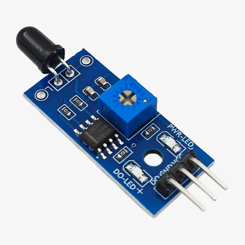
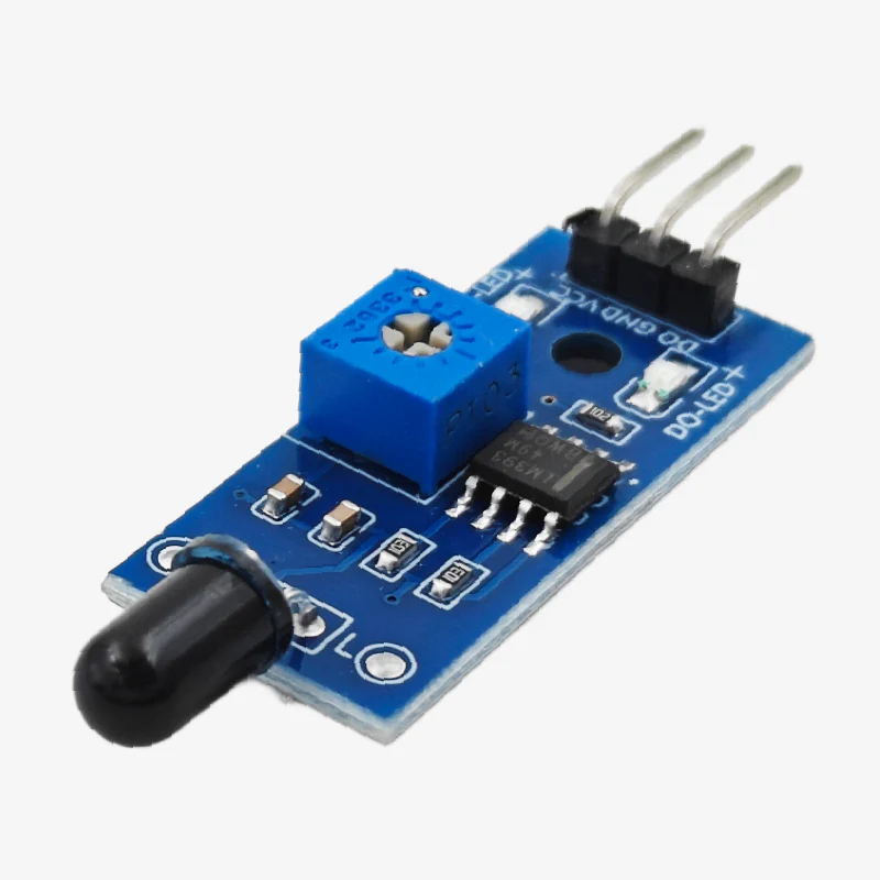
This flame sensor or fire sensor module works on the concept that when a flame or fire is burning it emits IR signals. This IR signal is then received by the IR receiver on the fire sensor module to detect the flame or fire.
The sensor has an operating voltage from 3V to 5.5V and has both digital and analog output. The sensitivity of the digital output can be controlled by the on-board potentiometer. Detection angle of sensor is 60 degree and range is theoretically 100cm but practically you can get upto 20-30cm
Brief Overview of IR Flame Sensor
This flame sensor consists of a photodiode, resistor SMD package of value 10K-2N0, capacitor SMD package of value 100nF – 2No, resistor SMD package of value 1K-2N0, potentiometer of value 10K- 1No, SMD led-2No.

Working of IR Flame/Fire Sensor Module
Case 1:
When the photodiode senses the IR waves which are emitted by the flame, its resistance decreases. The decrease in resistance depends on the intensity of the IR waves generating by the flames. If the flames are generating higher intensity of IR waves, the photodiode will act as a short circuit and offer minimum resistance towards the incoming voltage. At this moment the voltage at the non-inverting terminal will reduce and becomes as same as ground potential. The pot which is connected to the inverting terminal can be varied to change the voltage appearing at the inverting terminal. This is done to change the sensitivity of the sensor. (If the potentiometer is kept at the minimum value, then the module is said to have high sensitivity. If the potentiometer is kept at the maximum value, then the module is said to have low sensitivity.) At this stage the voltage at the non-inverting terminal is lesser than the voltage at the inverting terminal (assume that the voltage at the inverting terminal is greater than the GND potential), which leads the output of the LM393 to be a low value (0V). At this stage, the indicator LED which is connected in between the Vcc and Output will start glowing as there is a potential difference between its anode and cathode terminal. The output is taken from the LM393 pin 1.
Case 2:
When there is no flame, the photodiode doesn't sense any IR waves. This leads to offer maximum resistance to the incoming voltage and act as an open circuit. This makes the voltage of Vcc to appear at the Non-inverting terminal. As the voltage at the non-inverting terminal is greater than the voltage at the inverting terminal (the voltage at the inverting terminal is low than the Vcc), the output of the LM393 will be a logic high value (5V /VCC ). At this stage, the indicator LED which is connected in between the Vcc and the Output will not be glowing as there is no potential difference between its anode and cathode terminals. The output is taken from the LM393 pin 1.
Note: When the sensor doesn’t sense any IR waves, its output is HIGH (5V). If it senses IR waves, its output will be a low value (0V).
Details & Craftsmanship
Every detail has been carefully considered to bring you the perfect product.

Details & Craftsmanship
Every detail has been carefully considered to bring you the perfect product.

Details & Craftsmanship
Every detail has been carefully considered to bring you the perfect product.

Details & Craftsmanship
Every detail has been carefully considered to bring you the perfect product.

Details & Craftsmanship
Every detail has been carefully considered to bring you the perfect product.
Description
This flame sensor or fire sensor module works on the concept that when a flame or fire is burning it emits IR signals. This IR signal is then received by the IR receiver on the fire sensor module to detect the flame or fire.
The sensor has an operating voltage from 3V to 5.5V and has both digital and analog output. The sensitivity of the digital output can be controlled by the on-board potentiometer. Detection angle of sensor is 60 degree and range is theoretically 100cm but practically you can get upto 20-30cm
Brief Overview of IR Flame Sensor
This flame sensor consists of a photodiode, resistor SMD package of value 10K-2N0, capacitor SMD package of value 100nF – 2No, resistor SMD package of value 1K-2N0, potentiometer of value 10K- 1No, SMD led-2No.
Working of IR Flame/Fire Sensor Module
Case 1:
When the photodiode senses the IR waves which are emitted by the flame, its resistance decreases. The decrease in resistance depends on the intensity of the IR waves generating by the flames. If the flames are generating higher intensity of IR waves, the photodiode will act as a short circuit and offer minimum resistance towards the incoming voltage. At this moment the voltage at the non-inverting terminal will reduce and becomes as same as ground potential. The pot which is connected to the inverting terminal can be varied to change the voltage appearing at the inverting terminal. This is done to change the sensitivity of the sensor. (If the potentiometer is kept at the minimum value, then the module is said to have high sensitivity. If the potentiometer is kept at the maximum value, then the module is said to have low sensitivity.) At this stage the voltage at the non-inverting terminal is lesser than the voltage at the inverting terminal (assume that the voltage at the inverting terminal is greater than the GND potential), which leads the output of the LM393 to be a low value (0V). At this stage, the indicator LED which is connected in between the Vcc and Output will start glowing as there is a potential difference between its anode and cathode terminal. The output is taken from the LM393 pin 1.
Case 2:
When there is no flame, the photodiode doesn't sense any IR waves. This leads to offer maximum resistance to the incoming voltage and act as an open circuit. This makes the voltage of Vcc to appear at the Non-inverting terminal. As the voltage at the non-inverting terminal is greater than the voltage at the inverting terminal (the voltage at the inverting terminal is low than the Vcc), the output of the LM393 will be a logic high value (5V /VCC ). At this stage, the indicator LED which is connected in between the Vcc and the Output will not be glowing as there is no potential difference between its anode and cathode terminals. The output is taken from the LM393 pin 1.
Note: When the sensor doesn’t sense any IR waves, its output is HIGH (5V). If it senses IR waves, its output will be a low value (0V).