The Story
The MAX7219 is a constant current LED display driver IC that can be used to drive 7-segment LED displays, 64x64 LED matrix or individual LEDs. It communicates with a microcontroller through a simple serial interface. The chip also has a built-in BCD decoder and 8x8 static RAM.
Specifications of MAX7219 IC
- 10MHz Serial Interface
- Individual LED Segment Control
- Decode/No-Decode Digit Selection
- 150µA Low-Power Shutdown (Data Retained)
- Digital and Analog Brightness Control
- Display Blanked on Power-Up
- Drive Common-Cathode LED Display
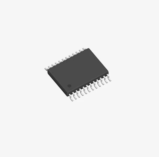
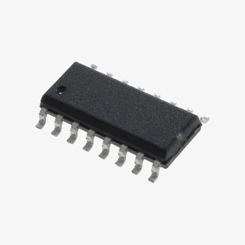
- 24-Pin DIP and SO Packages
MAX7219 Pinout Diagram

MAX7219 IC Pinout Description
|
PINS |
NAME |
DESCRIPTION |
|
1 |
DIN |
Serial data input |
|
2, 3, 5 – 8, 10, 11 |
DIG0 – DIG7 |
Current sink for each common cathode pulled high in shutdown |
|
4, 9 |
GND |
Chip ground, connect both pins |
|
12 |
LOAD |
16-bit data is latched to the internal memory |
|
13 |
CLK |
Serial clock input, 10MHz max. Data is shifted in on the rising edge and shifted to DOUT on falling edge |
|
14 – 17, 20 – 23 |
SEG A – SEG G, DP |
Current source for seven segments and decimal point |
|
18 |
ISET |
Source current set pin |
|
19 |
V+ |
VCC, 5.5V max. |
|
24 |
DOUT |
Serial data output for daisy-chaining |
MAX7219 Dot Matrix Display IC
The source current limit for the LEDs is set by connecting a resistor between VCC and the ISET pin. The source current is typically 100 times the current into the ISET pin. The minimum allowed resistor value is 9.5K, which sets the segment current to 40mA. The intensity of the LEDs can also be controlled digitally by writing to the intensity register. The full brightness is set by the resistor between VCC and ISET, and the minimum is 1/32 of the peak current. The intensity is controlled by 16 intervals.
The MAX7129 has a 16-bit input register. The first 8 bits, D0 – D7 are the data bits. D8 – D11are the four address bits. D12 – D15 are not used. D15 is the first bit received, i.e. the input is MSB first.
The display test mode turns on all the LEDs in the display to maximum intensity. To enable display mode, write D0 1 to address 0xF. To disable test mode, write D0 0. The digit registers are responsible for each of the 8 digits connected to the display. Each digit D0 – D8 has the address 0x1 to 0x8.
Shutdown turns the internal current sources off and puts the chip in a low power state which consumes only 150uA. The chip can be shut down by writing D0 0 at address 0xC.
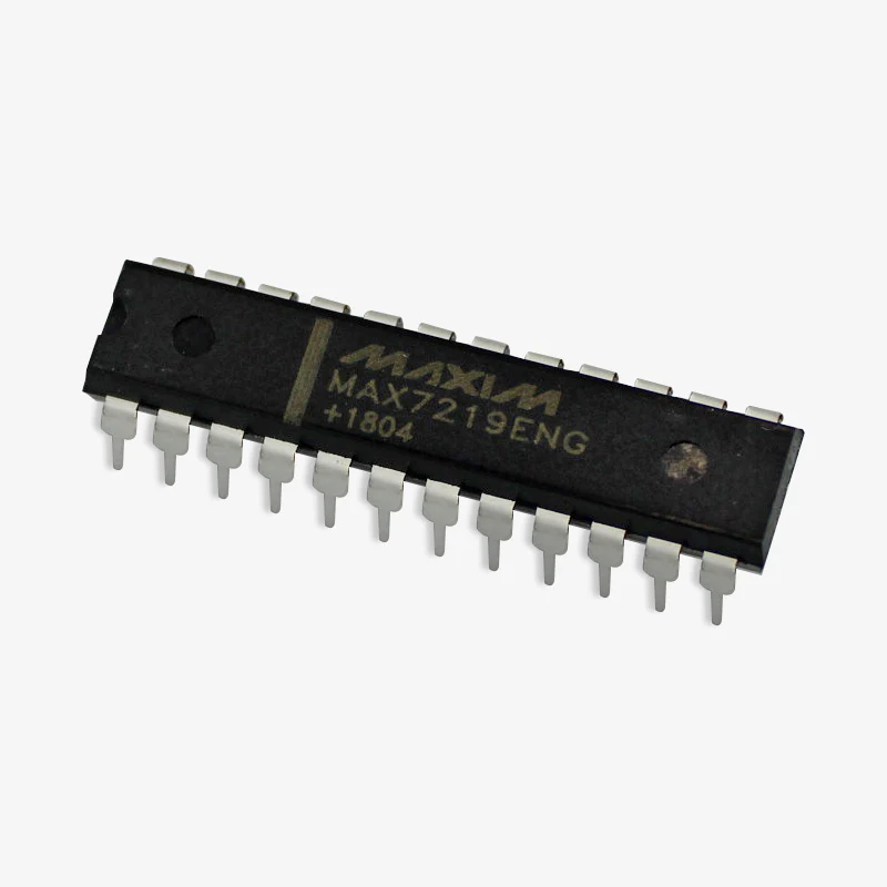
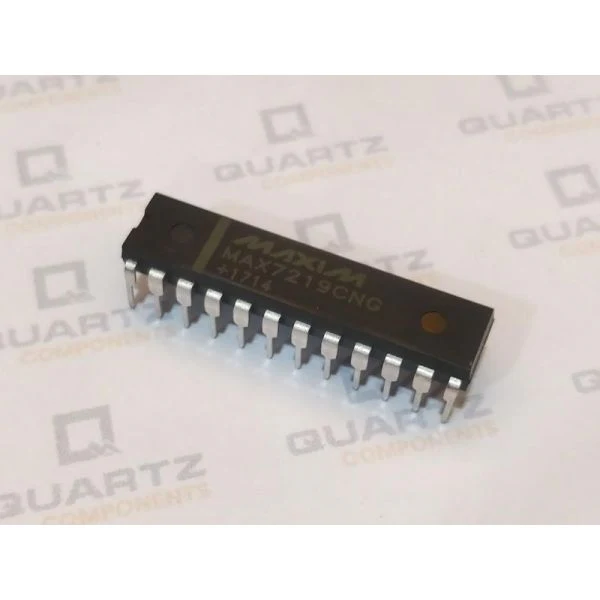
MAX7219 Package Outline
The IC is available in the standard 24-Pin DIP Package which is breadboard friendly. The dimensions of the same are shown below.

Further Reference
- MAX7219 datasheet

Details & Craftsmanship
Every detail has been carefully considered to bring you the perfect product.
Details & Craftsmanship
Every detail has been carefully considered to bring you the perfect product.
Description
The MAX7219 is a constant current LED display driver IC that can be used to drive 7-segment LED displays, 64x64 LED matrix or individual LEDs. It communicates with a microcontroller through a simple serial interface. The chip also has a built-in BCD decoder and 8x8 static RAM.
Specifications of MAX7219 IC
- 10MHz Serial Interface
- Individual LED Segment Control
- Decode/No-Decode Digit Selection
- 150µA Low-Power Shutdown (Data Retained)
- Digital and Analog Brightness Control
- Display Blanked on Power-Up
- Drive Common-Cathode LED Display
- 24-Pin DIP and SO Packages
MAX7219 Pinout Diagram
MAX7219 IC Pinout Description
|
PINS |
NAME |
DESCRIPTION |
|
1 |
DIN |
Serial data input |
|
2, 3, 5 – 8, 10, 11 |
DIG0 – DIG7 |
Current sink for each common cathode pulled high in shutdown |
|
4, 9 |
GND |
Chip ground, connect both pins |
|
12 |
LOAD |
16-bit data is latched to the internal memory |
|
13 |
CLK |
Serial clock input, 10MHz max. Data is shifted in on the rising edge and shifted to DOUT on falling edge |
|
14 – 17, 20 – 23 |
SEG A – SEG G, DP |
Current source for seven segments and decimal point |
|
18 |
ISET |
Source current set pin |
|
19 |
V+ |
VCC, 5.5V max. |
|
24 |
DOUT |
Serial data output for daisy-chaining |
MAX7219 Dot Matrix Display IC
The source current limit for the LEDs is set by connecting a resistor between VCC and the ISET pin. The source current is typically 100 times the current into the ISET pin. The minimum allowed resistor value is 9.5K, which sets the segment current to 40mA. The intensity of the LEDs can also be controlled digitally by writing to the intensity register. The full brightness is set by the resistor between VCC and ISET, and the minimum is 1/32 of the peak current. The intensity is controlled by 16 intervals.
The MAX7129 has a 16-bit input register. The first 8 bits, D0 – D7 are the data bits. D8 – D11are the four address bits. D12 – D15 are not used. D15 is the first bit received, i.e. the input is MSB first.
The display test mode turns on all the LEDs in the display to maximum intensity. To enable display mode, write D0 1 to address 0xF. To disable test mode, write D0 0. The digit registers are responsible for each of the 8 digits connected to the display. Each digit D0 – D8 has the address 0x1 to 0x8.
Shutdown turns the internal current sources off and puts the chip in a low power state which consumes only 150uA. The chip can be shut down by writing D0 0 at address 0xC.
MAX7219 Package Outline
The IC is available in the standard 24-Pin DIP Package which is breadboard friendly. The dimensions of the same are shown below.
Further Reference
- MAX7219 datasheet